Pira CZ Stereo Encoder for FM broadcasting
This stereo encoder advisedly does not contain any preemphasis circuit. Remember the key fact: a compressor/limiter/clipper device must be always present between the preemphasis circuit and the stereo encoder or modulator. Only this configuration ensures loud sound without exceeding the maximum frequency deviation limit (75 kHz). The stereo encoder is designed to provide really good sound. This always needs to use the compressor/limiter/clipper device where the preemphasis is precisely assured. The Pira CZ Compressor/Limiter/Clipper is highly suitable for this task.
Basic block diagram:
Characteristics:
- Signal overshooting prevention
- Low noise and distortion
- No adjust (only pilot tone level and output level)
- High channel separation and spectral purity in common operation
- RDS input and pilot sync. output makes easy to connect any RDS encoder
- Microcomputer controlled, hex file provided for free
- All parts are easy to buy (incl. crystal)
| Supply voltage: | 9-16 V (stabilized) |
| Quiescent supply current (12 V): | 34 mA |
| Audio 19 kHz rejection: | 40 dB |
| Channel separation at 1 kHz: | >55 dB (see details) |
| Subcarrier rejection: | >60 dB |
| Pilot sampling frequency: | 1.843 MHz (19 kHz x 97) |
| Subcarrier sampling frequency: | 1.843 MHz (38 kHz x 48.5) |
| Pilot sync. output: | TTL |
| Max. audio input voltage: | 5 V pp (1.75 V rms) |
| Pilot tone level: | linear adjustable 0-0.5 V pp |
| Output voltage gain: | linear adjustable 0-1.5 |
| Audio input impedance: | 2000 ohm |
| RDS input impedance: | 1000 ohm |
| MPX output impedance: | 500 ohm |
| Pilot sync. output impedance: | 10000 ohm |
| Signal-to-noise ratio: | >70 dB |
Schematic diagram:
Part list:
U1-U3 - TLC272, TS272
U4, U5 - 74HC4053 (74HCT4053)
U6 - 7805
U7 - PIC18F1220-I/P with stereo.hex file inside
Y1 - Crystal 7.3728 MHz (7.372 MHz)
SW1 - Button
L1, L2 - Coil 15 mH (09P-153J)
RN1, RN2 - SIL resistor network 3x 1k (discrete, 6 pin)
C1, C2 - 47p (C)
C3, C4, C5, C9, C24, C33-C35 C37 - 100n (C)
C6 - 82p (C)
C7, C19, C20, C30, C31 - 270p (C)
C8, C11, C14, C22, C23 - 220u/10V (E)
C10, C21, C25, C32 - 560p (C)
C12, C36, C38, C39 - 100u/10V (E)
C13 - 470u/25V (E)
C15, C26, C40 - 22p (C)
C16, C27 - 2n7 (C)
C17, C28 - 4n7 (P, 5%)
C18, C29 - 10n (C)
R1, R24 - 20k (1%)
R2-R9, R30, R31, R38, R39, R49, R50 - 2k (1%)
R10 - 160k
R11 - 330k
R12, R16, R27-R29, R40-R42 - 39k
R13 - 82k
R14, R17, R18, R20, R21, R25, R32, R43 - 10k (1%)
R15, R26 - 1k
R19 - 470R
R33, R34, R44, R45 - 30k (1%)
R35, R46 - 16k (1%)
R36, R47 - 47R
R37, R48 - 680R
R22, R23 - Trimmer 5k
HEX file: stereo.zip (WDT: on, Osc.: HS PLL, MCLRE: RA5), version 2.0.
Suitable free PIC programmer is for example here: http://www.members.aon.at/electronics/pic/picpgm/. Actually Pira CZ does not provide the PIC programming, PCB nor complete kit sale for this device.
Adjusting elements description:

Pilot level adjustment: The pilot level should be set to 9 % of the total deviation (75 kHz), measured in peak-to-peak values. For example, if audio input level is 2 V pp, set the pilot tone level to 0.2 V pp (the adjustment is linear with the max. of about 0.5 V pp).
Output level (gain) adjustment tip: If possible, it's recommended to set high output level and adjust lower sensitivity on the transmitter/exciter rather than set low output level and adjust high sensitivity. This way gives getter S/N ratio. Is it clear?
Note: The output level adjustment has no effect on pilot-to-audio ratio.
Mode selection: Click and hold the button until the mode change is indicated by acoustic signal (number of beeps indicates the mode set). The device will remember the setting.
Mode table:

Mode 1 is the default and recommended. Mode 2 switches to monaural operation. Modes 3 to 5 can compensate transient characteristics in some cases and improve channel separation, but have no reason for nonspecialists.
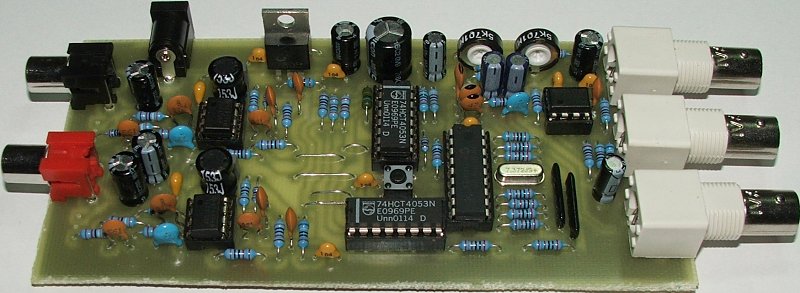
PCB:
Connection to the RDS encoder:
Source : http://pira.cz/eng/stk2en.htm
Comment Form under post in blogger/blogspot